
How I built a neural network controlled self-driving (RC) car!
TweetAugust 6th 2017: This project is very old and pretty much obsolete now. I hope it inspires you to learn about ML or build something fun, but I urge you not to replicate this build, but rather to head on over to the much more modern Donkey Car project once you've finished reading!
Updated January 11th 2013: Watch my BACON talk on this project on YouTube.
Updated January 2nd 2012: the source code is now open source and available on github.
Recently, I have been refreshing my knowledge of Machine Learning by taking Andrew Ng's excellent Stanford Machine Learning course online. The lecture module on Neural Networks ends with an intriging motivating video of the ALVINN autonomous car driving itself along normal roads at CMU in the mid 90s.
I was inspired by this video to see what I could build myself over the course of a weekend. From a previous project I already had a cheap radio controlled car which I set about trying to control.
The ALVINN system captures video frames every couple of seconds and passes them to a (series of) neural networks which have been trained by watching a human drive in similar environments. The trained neural network can then be passed live video frames and will predict how to steer to stay on the road ahead! I figured I'd do the same with my scaled down version. I needed a system which could operate in two modes:
- Record — The system captures video frames and the control input from a human driver (me!) and records them for later use to train the neural network.
- Drive — Captures live video frames, passes them to a trained neural network which makes predictions about how to drive/steer which are sent to the car by radio control - hey presto, a self driving car!
Design
The system should be able to record video from the car, pass frames to a neural network and control the car's steering / motors. The "obvious" way to do this might be to mount an Android phone on the car, gathering video frames and making neural network predictions locally on the device, hacking the car to be controlled from the onboard phone using an Arduino based Android ADK board, with data recorded and transferred to a computer for training.
Unfortunately, ADK boards require enough juice to keep the phone powered over USB and the weight of additional batteries would make this cheap and cheerful car struggle. Instead, I opted for a design which barely modified any of the components involved:
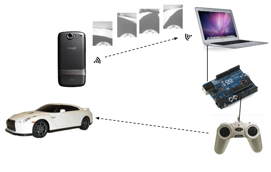
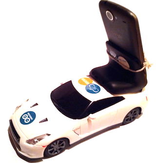
- Android phone — mounted on the car, captures video frames of the road ahead using its built-in camera at ~15 fps. An app running on the phone connects to a server running on a laptop computer via wifi and streams 176x144 grayscale video frames across the connection.
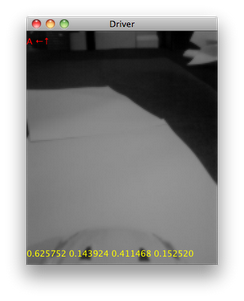
- Computer — runs a little Java app called "Driver" which acts as both a TCP server, receiving streamed image frames from the phone and a user interface allowing a human driver to control the car with the cursor keys or mouse. In record mode, the video frames are saved to disk, labelled with the current control input coming from the human driver. The neural network is trained using these labelled frames in a separate environment on the computer. Trained parameters are saved out to files which are in turn read by the Driver app... which in auto mode can feed incoming video frames directly to the neural network and steer according to its predictions, by sending instructions over a serial interface connected to an...
- Arduino Uno — connected to the computer via USB and hacked to connect to and simulate keypresses on the car's radio controller PCB (as described below).
The Neural Network
As on the ML course, the Neural Network is trained using an octave program, and I didn't stray too far from the set up used there. The diagram below shows the architecture of the network I used. Here we have 25345 units in the input layer - 25344 units which are fed the brightness value of an individual pixel in the 176 x 144 video frame (176x144 was the lowest resolution the camera on my phone supported in preview mode) and a bias unit. I chose to use 64 non-bias units in my hidden layer - this choice is fairly arbitrary, but I found that my initial choice of 256 took a pretty long time to train, and 8 units were not expressive enough to drive the car successfully. Crucially, there are four units in the output layer - one corresponding to each of the instructions we can send the car - go forwards, backwards, left or right.
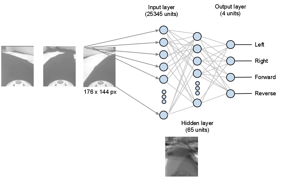
Here comes the magic - the network is trained using backpropagation which produces weights corresponding to the contribution each input layer unit makes to the activation of each of the hidden layer units, and the contribution each hidden layer unit makes to the activation of each of the output layer units. There's no explicit image processing going on here - the network literally figures out what kind of patterns in the input video frames are useful in making decisions about how to drive the car, based on minimizing the numerical error between the current prediction and all of the recorded examples. The little frame at the bottom of the diagram below is a visualization of the weights assigned to each of the pixels in the input layer as they contribute to just one of the hidden layer units - you may be able to see here that this unit corresponds to some kind of edge detection in the middle distance broadly sweeping to the left or right.
To make predictions in auto mode, I also implemented the same network topology in Java (making use of the Apache Commons Math Library for linear algebra). NeuralNetwork.java contains the interesting code and is a generic neural net implementation you could use for any three layer network (and also contains code for parsing a RealMatrix from an octave .dat file). To test the correctness of this implementation, NeuralNetworkTest.java checks that the predictions from this code are virtually identical to those made with the same input data and network parameters under the octave implementation. The Driver app uses this Java implementation, set up with network parameters loaded from files written by the octave script at the end of the training process.
Radio Control with Arduino
For a previous project, I had controlled this car with a PS/2 mouse connected to an Arduino UNO. This time, I extended that design so that commands sent over the USB / Serial interface could be sent to the car via its original controller.
Choice of car
 I bought the cheapest RC car I could find - this one if you want to get the same - it cost about £10. Pretty much any cheap car will do, as long as the controller is a push button on/off type rather than a continuous control. The hack is pretty simple - modify the radio control unit (car stays unmodified) so that instead of a human pressing the buttons, the arduino board will press them for us based on the value received over the serial port.
Figure out how the RC controller works
Take the RC controller apart and figure out how it works. Expensive radio controlled cars have servo motors for steering and variable speed control on their main motor, but a cheap car like this just has on/off switches for each of forward / backward / left and right. You can follow the tracks from each side of each switch to the nearest solder joint on the original board. Find the pads for each switch and confirm with a multimeter that the solder joints are the correct ones - when the switch is pressed, the resistance between the two relevant joints will be zero. Once you've identified the joints that matter, attach patch wires to each point with a soldering iron. The controller I used had a common ground (blue wire in the photo below) which the pads for up/down left/right were being connected to when the relevant switch was pressed. In the photo, you can see that I have traced these connections back to the point where solder joints already existed and attached wires (orange, yellow, white, red). It is a good idea to use different coloured wire for each of the directions so you can keep track of which one is which when working on a breadboard.

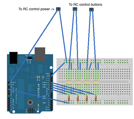
Once I got it working, I chose to remove the PCB from the original controller housing altogether and instead of powering it with 2 x AA batteries, I fed it 3.3V from the Arduino board (so all power for this unit comes over USB from the computer). To switch the connections from software running on the Arduino board, we need to build a simple circuit on a breadboard to allow an Arduino pin to drive each 'button' without being physically connected in a circuit [1] - we can use optical isolators for this - the opto-isolator part I used was a 4N35. You need to build the below circuit four times (once for each direction). The common ground from the RC controller will be connected to pin 4 of the 4N35 and the direction switch lead you soldered on will be connected to pin 5. The Arduino pin for turning on the controller switch for the given direction will be connected to pin 1 on the 4N35.

Fully built out on a breadboard it will look like this:
Arduino sketch
Finally, we need a firmware sketch to run on the Arduino board. You can see the full source for this on github, but the key part is this little section inloop() :
 if (Serial.available() > 0) {
    incomingByte = Serial.read();

    left = right = forward = back = LOW;
    if (incomingByte & 0x01) {
      left = HIGH;
    }
    if (incomingByte & 0x02) {
      right = HIGH;
    }
    if (incomingByte & 0x04) {
      forward = HIGH;
    }
    if (incomingByte & 0x08) {
      back = HIGH;
    }
    ...
    digitalWrite(leftPin, left);
    digitalWrite(rightPin, right);
    ...
  }
Which reads a byte from the serial interface and decodes it to determine which buttons to push on the remote control which are written out as HIGH signals on the arduino output pins connected to the opt-isolators above. You may also notice in the source that I chose to pulse the forward direction for 250 ms followed by a 500 ms pause - this was done simply because the car I used was very fast and difficult to drive round a small circuit - you might like to experiment with different values or remove this altogether if you try with a slower car.
And, putting it all together, here's another video of the car in action: